
A battery powered minimal parts DIY spring reverb. Delivers cheesy tin-can-bliss by the bucket.
This document documents the current status of the project. It still might change over time.
you can hear a short test here:
(This is a Doepfer dark energy ii directly through the spring reverb into the audio interface.)
A short explanation video is here.
This is one of my weekend projects. It works for me but it is merely a basis for further experimentation. There are many ways from here (mostly charted territory I assume, though). I am not an electrical engineer. The circuit might very well be badly designed or faulty but it does what I hoped it would do better than I thought it would.
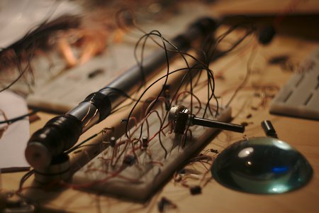
For a spring reverb you need to excite the spring(s) with an audio signal at one end and at the other end pick that signal up again. Usually this is done by attaching the spring to a magnet and then exiting that magnet through the magnetic field of a coil at one end and picking the vibrations up with another coil at the other end.
Here we will do this the way a guitar pick up or a sustainer works: Winding a coil with lacquered copper wire around a tube containing the spring and placing a magnet next to it makes a pickup that will detect the vibrations of the (conducting!) spring. If on the other hand the coil is driven by a small amp the changing magnetic field will excite the spring.
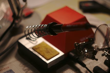
Besides the springs, couple of screws , and the housing I had everything needed lying around, actually. Of course you will need a soldering iron and some basic soldering skills, and solder. Apart form that:
An aluminum tube approx. 35cm long with 2cm diameter. A (chain of) conducting spring(s) that fit inside with some space around and low to medium tension. Some means to fix them at the tube ends, like these modified screws. Lacquer coated copper wire with .2mm diameter, some insulating tape, and two fridge magnets.
If you are going to make the end attachments the way I did, you will need a dremel to cut the screws but maybe you can find a small hook or something instead.
Resistors, capacitors and two ICs (a TL072 dual op-amp and a LM386-3) as given in the bill of material.
Not on the list: A 50k linear pot some wire to connect the board with the coils and the sockets, 2 TRS jacks (one stereo) for input and output, a battery connector and/or a power supply socket, and some strip-board. Optionally a LED and a foot switch for bypass.
Strictly speaking not necessary but highly recommended if you intend to actually "use" the device. It is best to place the tube in some kind of suspension since spring reverbs are sensitive to ambient sound and vibrations. I put mine in a plastic tube with foam support at both ends. and a predrilled 125b aluminium housing for guitar effects, but a simple plastic compartment (for house electricity) works equally well.
On the other hand: tapping on the aluminum tube produces interesting sounds on its own and maybe you want to keep the tube "hitable"... For my housinf I used an orange (had to be :) ) plastic tube (intended for tungsten lamps) to suspend the tube in, some tube insulation foam for suspension, two piping clamps to hold the tube, a pre-drilled 125B aluminium housing with a footswitch and status LED and some green pvc tube (from the aquarium section of the home depot).
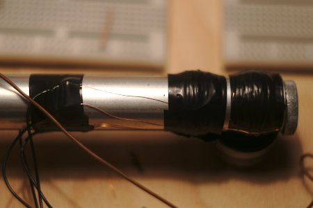
On each side of the tube I wound the copper wire to a coil. I ended up with 220 turns and ~10Ohm on the driver side and 500 turns and ~20Ohm on the pick up side. A layer of tape makes this easier. I wraped the with another layer of tape to fix it.
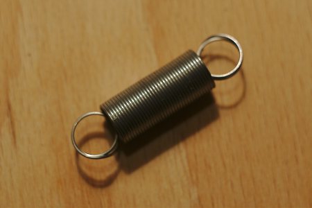
Next I chained 5 of these hardware store springs:
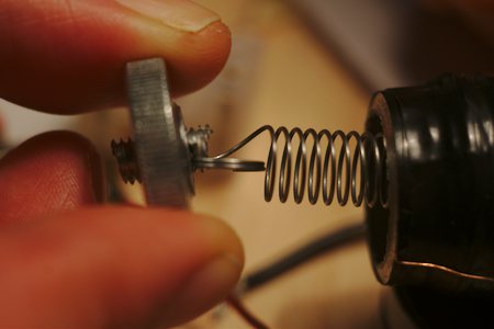
I cut two bits off a M5 screw and made slits at one end so that they can serve as hooks for the springs. The bits get screwed into these nuts until they fix the spring tightly:

(preliminary -- still need to be double checked)
The circuit is kept very simple on purpose: I am not knowledgeable enough to design fancy ones. The layouts are mostly textbook (or data sheets).
First the signal gets filtered a little bit: The 1MOhm resistor to ground prevents clicks and together with the 10nF capacitor acts as a highpass filter with a roll-off frequency of about 16Hz. The 1nF capacitor to gorund and the 4.7k resistor on the other hand form a lowpass that rolls off above 33kHz. Then the input signal gets biased to 4.5V and proceeds into an op-amp: The first half of a TL072 dual op-amp, wired for non-inverting amplification with a gain of 1 so this is just impedance conversion. One might get away omiting it completely - I did not try. From there the signal goes into a mixing pot and into the lm386 power amp with a gain of 50 (the schematic is basically drawn from the data sheet). Since the input of the LM386 is biased to ground we need not care about that ourselves. The amplified signal drives the spring. The signal from the pickup on the other end of the tube goes into the second half of the TL072. Again wired for non-inverting amplification this time with a gain of 1+100/1. The amplified pickup signal (containing the all wet reverb signal) goes to the other side of the mixing pot.
You may want to breadboard the circuit first and tinker with some of the values.

There you have it: a bare bones spring reverb with dry/wet control that will rattle and mumble to your taste.

I cut the orange tube to length (actually shorter than the reverb tube since the magnets would not fit in and drilled two 6mm holes as cable outlets. Two additional pieces were cut and slit open so that they can fit around the part wit the magnets. I placed the reverb tube in there (ensuring that the driver and pick up cables are exiting throu the drilled holes. The reverb tube is hold into place just by some insulation foam at the ends. The orange tube in turn is fixed on the 125B case by the two tiping clamps. One of the screws also doubles as holder for the stripboard inside.
The housing has holes for TRS Jacks and power on the sides and holes for 3 pots a status LED and a foot switch on top. I used them for the two piping clamps, two green pvc tubes (for cables and a LED), the pot, and a foot switch. the switch and LEd are wires in the usual active indicator and true bypass way.
Try different springs and spring combinations as well as different tensions.
You might want to tinker with the gain levels first. The driver amps gain is set to 50 in the schematic. Removing the cap and resistor between legs 1 and 8 of the LM386 will reduce it to 20 removing the resistor only will raise it to 200 (different resistor values will allow any gain you see fit). The gain of the second op-amp stage that amplifies the pickup signal is set by the ratio of the resistors Ra and Rb. Again the values are fitting for me but your mileage may vary.
It is easy (and maybe worth-wile) to add some high frequency roll-off to the effect. This can be incorporated in the second op-amp feedback loop. A capacitor of 15pF will give a roll-off frequency of ~2200 Hz.